Fitting an Apex'i S-AFC into the Nissan 200sx S14 & S14a
I've actually removed this now as I never had the time or cash to get it fully setup, although it was pretty.
Tools Required:
Philips & Flat screwdriver, pliers, wire stripper or stanley knife, electrical tape.
1. Disconnect the battery earth lead
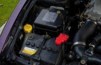
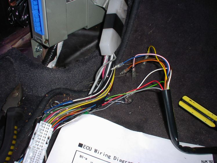
2. In the passenger footwell, remove the plastic cover to reveal the ECU
{picture}
3. The connector is bolted on and will need to be unscrewed. Likewise it can't be pushed back on, it needs to be screwed back in place.
At this point I actually took the passenger seat out because it was cold and I wanted to do it with the door closed. For you 6 footers out there it probably won't make any difference. To take it out, just undo the 4 bolts either corner.
The connector has all the ECU wires coming out of it and should be covered by a bit of plastic polythene. Just pull this polythene apart to reveal the wires. You will find it a lot easier if you pull the plastic clip down of the back of the ECU to give more room more manoeuver with the wires
Finally, the connector has a clear plastic cover on it to protect the wires from being pulled, this needs to be removed by inserting a flat headed screwdriver into the 4 clips whilst pulling it away gently.
4. The next bit is the wiring. Take your time on this and check you've got the correct wires and after you've done that, check again. Also check that you're using the correct diagram. These two pics are from the Apex'i website (downloadable PDF files here: www.apexi-usa.com/documentation.asp ). I've redone the N3-a one using the correct colours for simplicity.
 |
 |
S14a
only |
S14
only |
The S14 is a hotwire car according to Apex'i meaning it uses an Airflow Meter to figure out how much air is coming into the engine so it can adjust the fuel accordingly.
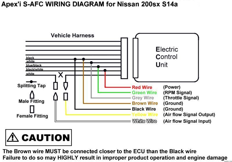
The above pic says it's for the S14a but will also be fine for the S14 but I can't guarantee that the ECU wires are the correct colours.
5. Okay, start stripping
I worked through the wiring diagram in this order: red, green, grey, brown, black, yellow & white.
First, locate the IG power wire coming from the ECU connector, and follow it down from the connector about 5 inches. Then for good measure, follow it back up again and compare it's position against N3a or N4a to make sure you've got the right one.
You need to strip the plastic cover of the wire all the way around for about 8mm CAREFULLY using a stanley knife/ wire cutter. Trim about 1.5cm of the wire cover off the end of the red Apex'i wire. Wrap the bare thread from the red wire tightly around the stripped bit of IG power wire, then place the splitting cap over the two wrapped wires. Press this closed very tightly with the pliers and check the connection is secure. Wrap some electrical tape around it and that's the first one done!
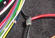
after a short while, it should start to look like this:
when you finally get to attaching the black & brown wires from the S-AFC, make sure the brown wire is attached closer to the ECU than the black wire. The manual also recommends having them about 1cm apart on the same wire. Don't attach them at the same point on the ECU earth wire!
6. Cutting the Airflow signal wire in half
Locate the white (S14a) airflow signal wire and cut it.
This wire is cut because this is the signal that is intercepted and altered by the S-AFC.
Make sure there's enough length either side to fit the male and female connectors. Strip the plastic cover off both ends of the cut wire back by about 5mm. On the end closest to the ECU, push the small clear rubber cover over the end and then attach the male fitting as so:
Do the same on the other end with the female fitting. It's really important to make sure you've got a good connection on these.
You can now attach the yellow wire from the S-AFC onto the male fitting and then attach the white wire from the S-AFC onto the female fitting.
That's it! The wiring's done. Carefully wrap the wires back up and put the plastic connector cover back on. Bolt the connector back onto the ECU nice and tightly.
7. Mounting the S-AFC
The next thing is to mount the unit. After thinking long and hard about it, I decided that there's too much theiving scum about and it has to go into the glovebox. Fitting was a piece of piss.
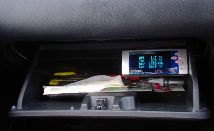
I unscrewed the glovebox (theres two screws at the bottom underneath), then using the Stanley knife I made a cut just big enough to pass the connector through from the S-AFC. I then just used the included mounting plate and stuck it upside down into the top-right of the glovebox, passed the cable through and stuck the S-AFC onto the mounting plate.
8. Finally, connecting and testing.
Plug the S-AFC connector into the connector coming from the ECU.
Put the negative battery lead back on.
Place keys in ignition and turn the circuit on. Don't start the engine at this point.
If the unit turns on successfully and after the intro screen goes into the menu, and there's no funny smells, noises, or smoke, you've done it correctly. If there's any problems, turn off the ignition, unplug the negative terminal of the battery again, unplug the S-AFC connector cable and take the white & yellow S-AFC wires out and plug the ECU white Airflow wire together again. That way it'll be back to normal.
A brand new unit won't have any settings in it so you'll need to tell it a bit about you're car.
On the main menu, go into the Etc. option. Then go into option 1. Sensor Type. Choose Hotwire. Press Next.
For the Sens No. screen, "IN" should be 5 and "OUT" should be 5.
For the Sens. Cal. screen, if you've not changed your AFM, you'll need to keep it at "IN"=1 and "OUT"=1.
For the Car Select
(option 2 on the main Etc. menu), the Cyl should be 4 and the Throttle sensor
type should be an arrow pointing to the top-right ![]() for 0-1V during closed throttle and 3-5V when open.
for 0-1V during closed throttle and 3-5V when open.
Option 3 on the Etc. menu is the graph scale. You should only need to change this so that option 2 (Ne) is set at 7000rpm. I think the engine cut-out on the S14a is at 7200rpm so this should be enough. If not, move it to 8000rpm.
Right, once you've done all that, start the bitch up and see how she runs.
Other than getting the fuelling professionally setup on a rolling road, that's it.
If you've got any questions on the above or noted any glaring errors, get in touch with me (kuddy) on the UK 200sx Owner's Club Forum.
NJK 11/02